28.1.1. Single Segment Line#
One of the important references for the catenary equation comes from the Mooring system engineering for Offshore Structures.
This shows the key formulas applying elasticity in the mooring line where each part of the mooring line change in x & z position is dependent on the starting tension combined with the weight of that section. These cause an increased tension and an elongation, which is the starting position for each next section.
Derivation of the formulas, ignoring the stiffness, is given in the course by Sebastian Schreier.
The catenary equation we will discuss considers elasticity of the line, no external loads and no bending.
There are two references we mention here which provide the theory and derivation of the equation.
The catenary equation describes a natural curvature of lines which is common in nature, very recognizable and in this example has been used by Gaudi to define the shapes within buildings.
In a catenary the tension in the line changes due to the weight of the line. Given that there is only own weight, the Horizontal component of the tension does not change and is the same at each segment. The change in Vertical force is caused by the increase in weight of the segment and this changes the angle of the line.
It is important to distinguish two aspects for moorings, namely
the mooring line shape and
force excursion.
The mooring line shape is the result of a single result of Horizontal and Vertical forces while a force excursion diagram provides the change in positions (shapes) when the forces change.
If we have a mooring line connected to an anchor on the seabed and the horizontal & vertical force are known at the end of that line, we should be able to derive the shape. We know that the horizontal force is equal at both ends (assuming that we do not account for friction on the seabed). The weight of the total line is equal to W and if V is less than W it would mean that there is a portion of the line lying on the ground. If V is equal or larger than W it means that the line does not lie on the ground and exerts a vertical force on the anchor. That situation is what we call a taut mooring line.
The notebooks provide further support for calculate the single and multiple line cases.
If we look at an example for the line shape, we know that of the total 80-meter line length, the suspended line is 60 meters long (note W of the suspended line = V).
With the equations we can derive the dx from the touch down point. Note that the first part is related to the length and stretch of the segment on the ground.
When looking at a force excursion characteristic, the movement of the fairlead causes a restoring force. Assume we move the fairlead in the horizontal axis distance over a distance dX, it creates a change in the shape and the touchdown point. The horizontal force is larger to get the line to this more stretched position and the vertical force is larger because more chain is picked up from the seabed.
If we take an example mooring line with an attachment at 200 meters above the seabed, with fairly heavy studless chain of 147 mm and a length of 600 meters, This is the resulting force excursion diagram.
A 600 meter line in 200 meter waterdepth can have 400 meters on the seabed with zero horizontal load. The vertical load is then the weight of 200 m chain. When moving the fairlead further from the anchor the horizontal load required to move the fairlead will start picking up while the vertical force starts increasing due to the amount of chain being picked up from the seabed. The tension which is the quadratic sum of horizontal & vertical force is also given in this graph as a blue line.
The example shows that the full chain mooring is very non-linear, it creates high tensions (larger than 100 mT) and the tensions increase fast at further excursions.
The stiffness at a chosen mean position (here at 500 m from the anchor with a tension of 1200 kN) is 15 kN/m.
It can be understood that in deeper water (more than this 200 m) a full chain mooring becomes prohibitive due to the weight of the chain. This is solved by adding other lighter line components. These are either steel wire rope or synthetic wire rope.
This example shows a line with a fairlead at 820 m from the seabed composed of 300 m chain on the seabed, connected to the anchor. The next segment is synthetic line of 1425 meter. The last segment is connected to the floater and is similar to the ground chain and is 60 meters long.
Click to expand the simplified catenary formula derivation!
This derivation is taken from OE44100: Floating Structures & Offshore Moorings by Sebastian Schreier, simplified without stretch and assuming no wave/current loads.
Step 1: Consider a small element
A mooring element of length \(ds\) has tension components \(F_x\) (horizontal) and \(F_z\) (vertical):
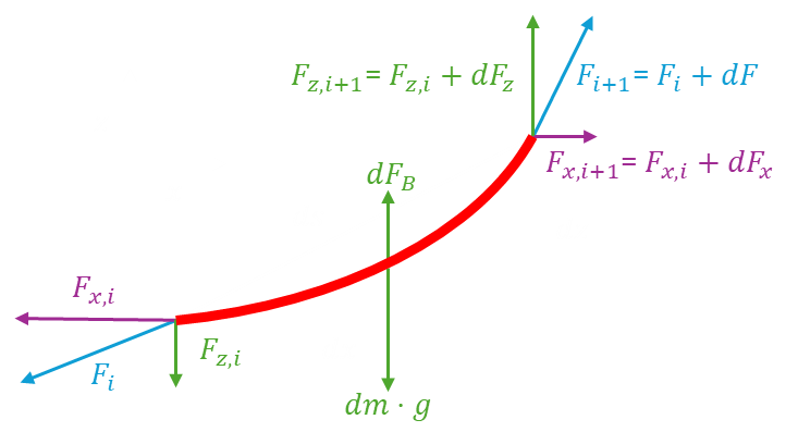
Assumptions:
No external horizontal forces → horizontal tension constant:
\( F_x = \text{constant}. \)Vertical equilibrium supports weight in water:
\( dF_z = w\, ds, \quad w = (\mu g)\,(1 - \rho_w/\rho_s). \)Geometry (slope relation):
\( ds = \sqrt{dx^2 + dz^2} = \sqrt{1 + (dz/dx)^2}\, dx, \quad dz/dx = F_z/F_x. \)
Step 2: Differential equation
From vertical force balance:
\( \frac{dF_z}{dx} = w \sqrt{1 + (dz/dx)^2}. \)Substitute \(F_z = F_x\, dz/dx\):
\( F_x \frac{d^2 z}{dx^2} = w \sqrt{1 + (dz/dx)^2}. \)Let \(p = dz/dx\), then
\( \frac{dp}{\sqrt{1+p^2}} = \frac{w}{F_x} dx. \)
Step 3: Integrate slope
Integrate \( \int \frac{dp}{\sqrt{1+p^2}} = \int \frac{w}{F_x} dx \quad\Rightarrow\quad \sinh^{-1}(p) = \frac{w}{F_x}x + C_1 \)
\( \text{so } dz/dx = p = \sinh\left(\frac{w}{F_x}x + C_1\right). \)
Step 4: Integrate position
Integrate \( z(x) = \int \sinh\left(\frac{w}{F_x}x + C_1\right) dx = \frac{F_x}{w} \cosh\left(\frac{w}{F_x}x + C_1\right) + C_2. \)
Boundary conditions at anchor: \(x=0, z=0, F_z=0\)
\( C_1 = 0, \quad C_2 = -F_x/w. \)Final shape:
\( \boxed{z(x) = \frac{F_x}{w} \left[\cosh\left(\frac{w}{F_x} x\right) - 1\right]} \)
Step 5: Key points for design
Horizontal tension constant: \(F_x\).
Vertical tension along the chain: \(F_z = F_x \sinh(\frac{w}{F_x} x)\).
Maximum tension occurs at fairlead.
Seabed contact if total chain length > suspended length.
Provides first-order estimates for mooring design, easy to visualize and teach.